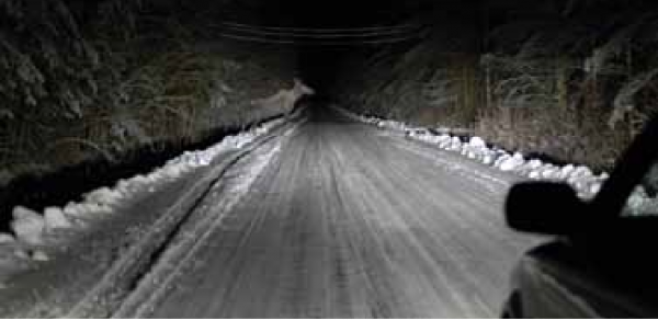
You can see it now, but what if you’re in the dark? Would you turn on your brights or leave it to chance?
The Case for More Power
It may be a cliché in the industry but it’s true: locating utilities is like being in the dark. You can’t see what’s underground, and even when aided by locating instruments, the picture you have is imperfect and requires some interpretation. Sometimes a “clearer” picture is easier to create than others, but certain techniques can help you when things are looking a bit fuzzy.
One general agreement on how to keep the picture clear is to use the lowest power setting on the transmitter. Using a lower power puts less current on the utility, and in theory protects yourself from dealing with the effects of unintentionally energizing other utilities.
However, a close look at the behavior of alternating current on a utility and the signal shows that using the lowest power output is not always optimal. In fact, taking an “always use the lowest power” approach can cause some unintended consequences out in the field, making the underground picture less clear. Here, we go over what really happens when you adjust your power output settings—and why locating with a higher power output isn’t always the invitation to disaster it’s made out to be.

Turning up the power on your transmitter gives you a better view into the underground. Think of driving down a winding country road at night. Using low beam headlights, you only see a portion of the road in front of you and very little on either side. If you switch to high beams, you see much more of the wilderness that surrounds you—and any obstacles that lie ahead.
Reasons for Using the Lowest Power
Beginning a locate with the lowest power is considered so important that several well-regarded names in the industry teach this method of locating. In its Best Practices Guide, The Common Ground Alliance instructs, “It is good practice to use the lowest frequency possible at the lowest power output possible to complete the locate.”
Radiodetection SPX’s abc, xyz of pipe and cable locating is one of the most comprehensive works on the theory and practice of utility locating. It states, “Successful location uses as low power a signal as possible. A high power signal couples to unwanted lines and spreads over the line. It is much easier to trace a low power clean signal along a line.”
The list of organizations that advise using this method goes on. There are good reasons for why this warning exists, including draining battery power and the possibility of energizing another utility. And if a low power works just as well as a higher power, there isn’t much of an argument to turn up the watts.
With all of that said, in many cases a lower power doesn’t do the job as well as a higher power. In the worst case, it can result in a mis-marked line. Here’s how it works.
Circuits and Bleed-Off
When you energize a utility with metal-to-metal contact, you create an electrical circuit from the transmitter to the utility, through the earth, and back to the transmitter’s ground. As current flows on the utility, some of it transfers into the soil. Commonly known as “bleed-off,” this energy transfer is directly proportional to the amount of current on the utility. Turning up the power puts more current on the utility, and more current on the utility results in more bleed-off into the soil.
Say you’re performing a locate and you’ve been transmitting at the lowest power setting. You’re standing over the utility and see that the current measurement on your receiver reads 200 mA. As you walk along the utility, the current reading on your receiver steadily drops. This is an indication of bleed-off. If you increase the power such that the current output increases to 400 mA, or twice the amount as before, you will see twice the amount of bleed off as you walk down the utility. The opposite scenario is also true: reducing the current on the utility by half results in half the amount of bleed-off, meaning it can never be eliminated entirely. But even with larger amounts of bleed-off, you’ll have more current to trace to begin with.
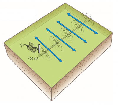
Morecurrent on the line results in more bleed-off.
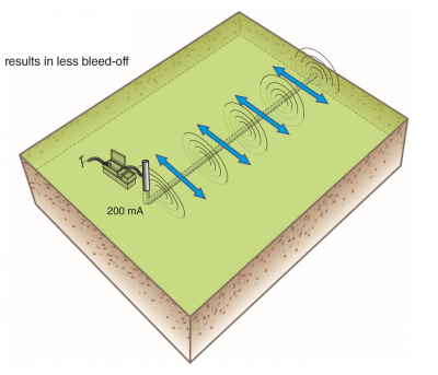
Less current on the line results in less bleed-off.
Return Current and Coupling
Once current transfers into the earth, it travels back to the transmitter’s ground through the “path of least resistance.” The path of least resistance is not a fixed route for current to take. It depends on soil conductivity, the presence of other conductive objects in the ground, and other factors. Often, the path of least resistance happens on a second nearby utility.
Indirect coupling is the phenomenon where current that has bled into the soil transfers onto another utility. For many within the industry, the term also refers to when the signal radiating from the target utility energizes another utility. Direct coupling, where current transfers through metal-to-metal contact, can also happen due to common bonding. In any of those scenarios, the undesired effect is that an additional utility is energized. This situation compromises the accuracy of the locate because of the interference caused by the second energized utility.
However, the likelihood of indirect coupling happening is determined by several factors, but not the amount of current on the utility or strength of the signal. Any amount of current that goes on the utility has to return to the transmitter somehow. If the frequency is high enough to overcome the resistance of a nearby utility, there’s a high chance of coupling onto it.
Whenever coupling occurs, the signal on the second utility is a fraction of what it is on the target utility. Increasing or decreasing the amount of current on the utility increases or decreases the signal strength on the second utility, but always at a fixed ratio. That means if the signal strength on the second utility is 50% of the target utility, that percentage doesn’t change if you adjust the power output. Similar to bleed-off, reducing the amount of current on the line does not eliminate interference, the strength of the interfering signal goes and down with the strength of the target utility’s signal.
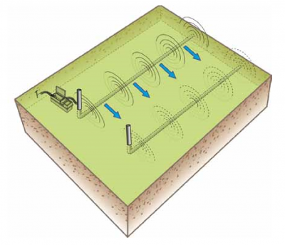
The path of least resistance back to the transmitter is often on a nearby utility.
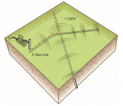
In this scenario, a 1’ deep CATV cable crosses over a 3’ deep gas line. The transmitter is hooked up to the gas line and the signal couples onto the CATV cable. Because the cable is so shallow, the strength of the signal on the cable is stronger than the gas line, which can lead operators to trace the cable instead of the remainder of the gas line. Turning down the transmitter power does not solve this issue; the strength of the cable’s signal remains the same percentage of the gas line’s signal. Instead, switching to a lower frequency and tracing the gas line to a logical endpoint such as a gas valve can prevent mismarking the gas line.
Seeing Clearly with a Stronger Signal
With our modern infrastructure, our airwaves are filled with electromagnetic radiation. Signals are constantly influenced by other signals.
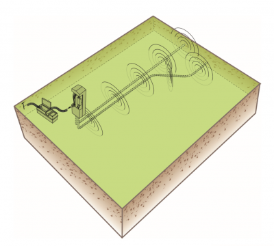
Telecommunications cables often share a common bond. When inducing onto a cable, the signal directly couples onto any other cable it shares a bond with at any frequency and any current output. Adjusting the current output increases or decreases the signal strength of the other cables in direct proportion to the target cable. It does not remove the chance of unwanted coupling.
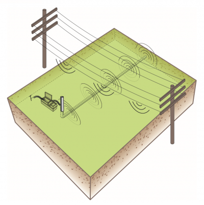
A strong signal on the target utility is less susceptible to noise from overhead power lines than a weaker signal is. Turning down the power makes the signal on the target line more difficult to trace.
Weaker signals are more likely to be drowned out by stronger signals—think of the increasing radio static in your car as you drive farther from the radio tower.
The purpose of adjusting any of the transmitter’s options is to make the signal as straightforward as possible to trace. Putting the least amount of current on the utility re-sults in a weaker signal coming off the utility, whereas putting more current on the utility can help you get a more accurate locate.
As any locating operator knows, it’s impossible to fully know the condition of what’s underground going into a locate. In cases where the utility has high resistance, such as when it’s damaged or corroded or when the circuit can’t be improved, the chances are greater that the signal will be too weak to trace, keeping you in the dark. And even if you haven’t coupled onto another util-ity, those weaker signals are more likely to be drowned out by noise—a not-so-unlikely possibility when tracing near overhead power lines or other signal sources.
Lastly, there are over 35 million miles of un-derground utilities in the United States, in-cluding abandoned utilities. Always putting the least amount of current on the utility can blind you to any unexpected utilities in the lo-cate area. If the signal on an abandoned util-ity is weak, it is easier to dismiss it as noise. A louder signal alerts you to something you didn’t expect.
Utility locating is a challenging profession. In an effort to simplify the process as much as we can, we sometimes go for the easiest route possible instead of the best route. It might be easiest to keep the transmitter power at the lowest setting and deal with tracing problems only as they arise. But boosting the power output is a proactive way to give yourself a clear signal to trace. After all, the world is only getting noisier.


