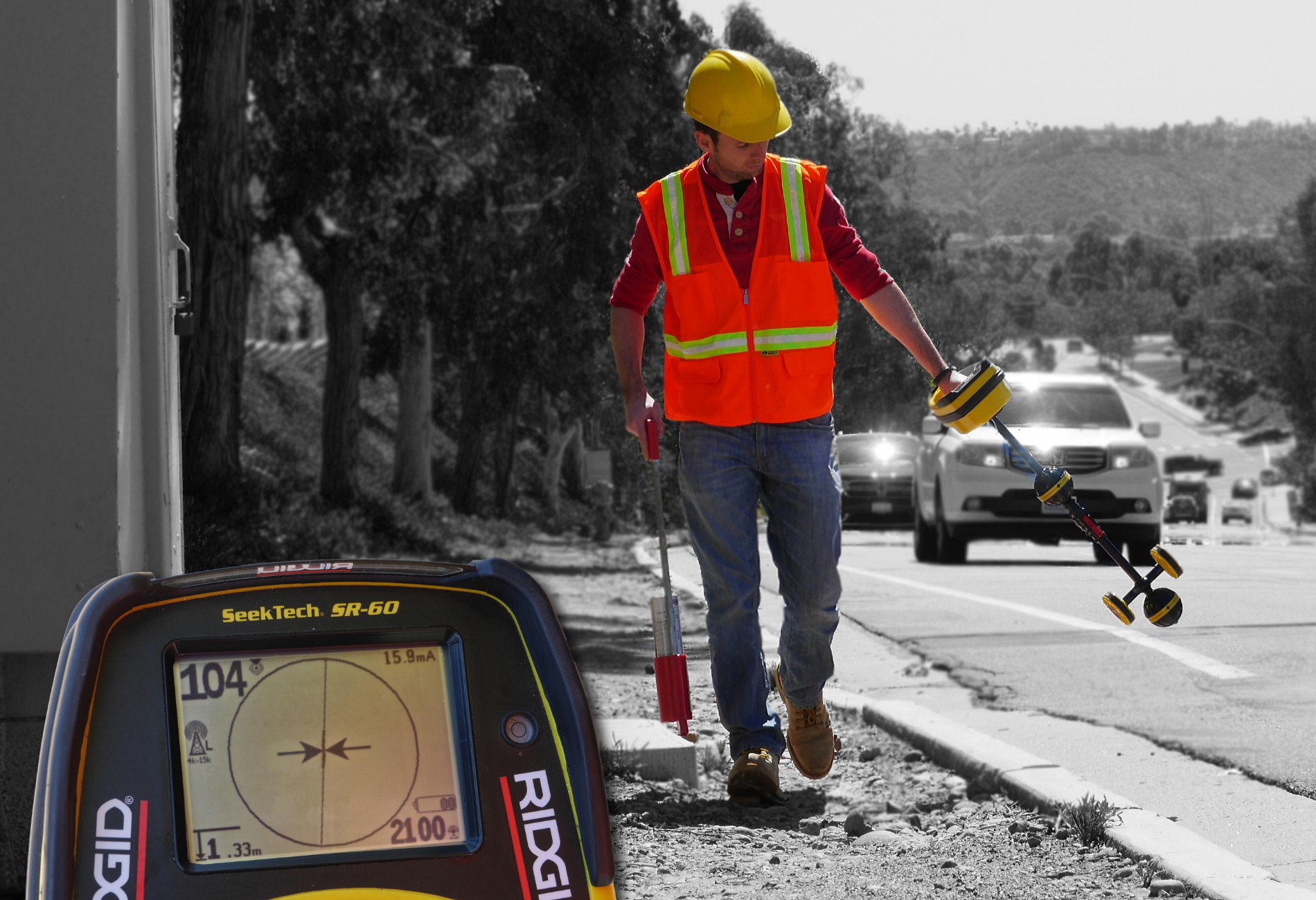
The Value of Locating with Gradients
Discussions among industry professionals about the science and technology of electromagnetic locating are often simplified out of necessity. We prioritize practical knowledge over in-depth physics explanations to ensure that the people out in the field have the information they need to get their jobs done. As a result, some technologies end up being left out of the discussion.
One of these often neglected technologies in the discussion is the ability to measure the electromagnetic field gradient. (For simplicity’s sake, let’s just refer to it as the “signal gradient.”) If it sounds new, it’s only because it doesn’t usually get named: the practice has been around since the Metrotech 810 hit the market in 1981. Since then, analyzing a signal by looking at the gradient has taken many forms, and has proven to be a particularly effective strategy for locating buried utilities.
So what is the electromagnetic signal gradient? How exactly do gradients work? And why are they so useful for utility locating? Bear with us: some physics, however light, lies ahead.
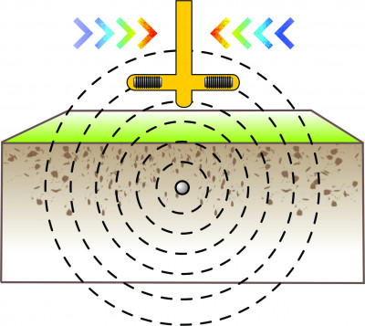
Let’s start off with an overview of electromagnetism. An alternating electrical current flowing on a utility produces a signal that radiates away in concentric cylinders – think differently sized cylinders stacked inside each other with a common center. This “signal” is actually an electromagnetic field that decreases in strength as it moves from its source. There are many meaningful bits of information we can gather about a signal: how strong it is at different locations, its direction, and shape.

Back to gradients. Broadly speaking, a gradient is a rate of change, which is one way to examine a physical property. You’re probably aware of concepts like temperature gradients and pressure gradients. They’re not exactly like a signal gradient, but the general concept is helpful.
Picture a hot iron in a blacksmith’s shop. When the blacksmith shapes an iron rod into another object, he first heats up the part of the iron to be worked on in the forge. As the iron heats, its color changes from dark red, to orange, to yellow, and lastly to white. The gradient is the increasing temperature in the direction from one end of the iron, held by the blacksmith, to the hotter end being hammered. Similarly, the signal gradient is the increasing or decreasing strength of the field in a given direction. If you’re standing directly to the left of an energized utility, the signal gradient increased to your left – towards the utility.
Any modern receiver can be said to measure the signal gradient. Here’s the catch: they can only do it in one direction (left-right) and it doesn’t happen automatically. If you’re familiar with finding a peak signal reading – the location where the receiver detects the strongest signal reading – the practice can also be called” tracing the gradient.”
Using a receiver with peak and null antennas, the operator holds the receiver perpendicular to the utility and swings it back and forth on either side of the utility’s estimated position. In peak mode, where the operator uses the receiver’s horizontal antenna(s), the receiver detects a maximum signal strength directly above the signal that diminishes in strength on either side. An operator traces the gradient simply by following the receiver readings to where the signal strength is greatest.
What separated the 810 from other receivers of its time was its ability to compare these left-right readings automatically and while being held still. It did this with two bottom horizontal antennas placed on either side of the mast. Similar to a depth reading, which compares readings between two stacked peak antennas, these two differential antennas provided left-right guidance by comparing readings between the left and right antennas. The 810 used left-right arrows to help the operator get positioned over the signal’s center, a design choice that set the standard for many receivers of today.
To put this in terms of the signal gradient, the 810 receiver can trace the signal gradient in one (left-right) direction automatically. It does so by comparing signal strength between the two left-right horizontal antennas. If the left antenna reads a greater signal strength than the right, the signal gradient increases to the left. If the antennas both read the same signal strength, the receiver is centered over the signal. This is sometimes referred to as “electronic null.”
The signal gradient increases towards the utility on either side of it. Meanwhile, left-right gradient antennas compare signal strength on both sides of the receiver automatically.
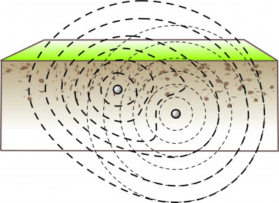
Interference from a nearby energized utility warps the signal shape and makes peak and null readings less reliable.
Complicated Locates with Gradients
Gradients as we’ve discussed so far do the following for us:
- Tell us how a signal changes (increases or decreases) in a given direction
- Provide us with the left-right direction in which signal strength is greater
- Let us know when the receiver is centered over the signal
As anyone in the industry knows, the reality of society’s buried infrastructure and mother earth are not nearly as clean and straightforward as we make them out to be in locator theory. A congested underground environment, particularly deep utilities, utilities that are damaged or corroded, poorly grounded utilities, and variable soil conditions affect the traceability of a signal, which can negatively affect outcomes.
Any of these conditions can warp the signal, potentially causing operators to locate so-called “false peaks” or “ghost peaks.” There are smaller peak readings that do not correspond to the buried utility’s position. (A disagreement between peak and null responses is one sign of a false peak.)
How can gradients help us with these all-too-common situations? Remember that a signal continuously radiates outward. If the receiver is positioned between a false peak and the true center of the signal, a gradient locator detects the stronger signal output coming from closer to the utility. This unique ability makes gradient locating more reliable that locating with and null alone in tricky conditions.
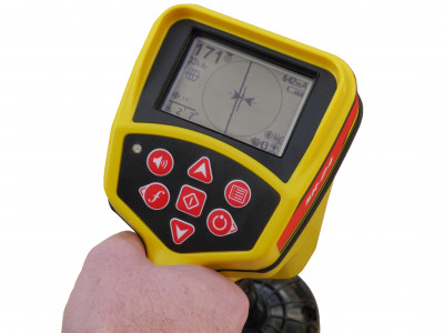
If you locate utilities with a more contemporary receiver, such as the RIDGID® SeekTech® receiver, you might be familiar with some version of the left-right arrows that show you the signal’s position relative to the locator’s. This boasts better accuracy than looking at signal strength alone. The more pieces of useful information you have about a signal, the better.
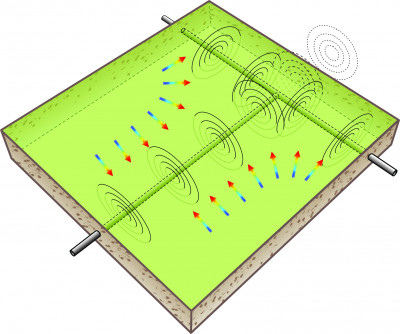
The full gradient is more sensitive to changes in the strength and direction of the signal, such as at a tee or an elbow.
Full Gradient Measurements
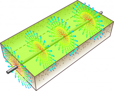
Current locating technology makes use of the gradient in one direction. But magnetic fields are three-dimensional. Signal strength decreases in all directions as the signal radiates from the utility. This means that the full signal gradient measures how the signal is changing in all directions.
If information about a signal is our best way to help operators estimate a utility’s position, measuring the full gradient can provide us with some substantial knowledge.
As the signal radiates outward, the full gradient points inward. It detects the direction of the greater signal strength from all direction – not just left-right.
Locating with the left-right gradient, either with the do-it-yourself method or with a set of left-right antennas, is a valuable asset for difficult locates. SeeScan is committed to building the latest locating solutions that provide the most information possible about an electromagnetic signal. Although locators capable of measuring the full signal gradient are not yet on the market, we continue to learn more about the science behind locating in our mission to build better locating technology.


